Elbow Links
This post explores elbow connector systematically. Elbow connector is a common UI pattern in whiteboard apps. A TypeScript implementation is available on Github Repo. Below is a demo of the implementation; try dragging the rectangles to see how the elbow connector automatically adjusts its path.
The Problem
"Elbow connector", or "right angle connector", connects elements using only horizontal and vertical segments. Despite its common use in whiteboard apps and diagramming tools, there is no formal specification for this pattern. This post aims to formalize the definition of elbow connector based on experience with various applications.
The task is to connect two points (p1, p2) using only vertical and horizontal segments. Optionally, these points might be associated with rectangles (rect1, rect2). The goal is to produce a list of points defining a connector path, implemented in a function signature like this:
            createElbowConnector(
                p1: Point,
                p2: Point,
                rect1?: Rectangle,
                rect2?: Rectangle,
                ): Point[]
Finding the optimal path isn't straightforward; it often relies on heuristics aimed at achieving a visually pleasing and natural feel. Implementations can vary across different applications.

Looking at these implementations, an initial idea is to avoid overlap with the rectangles. React Flow, a popular library for building node-based applications, seems not to consider this. Google Drawings encounters issues in certain corner cases, while FigJam strictly avoids overlap. Both Google Drawings and FigJam likely involve pathfinding, potentially at the cost of implementation simplicity, whereas React Flow opts for simpler path generation. Does FigJam look better than React Flow? Opinions may vary, which complicates finding a formal definition for elbow connectors. This post will focus on the FigJam version since it is less discussed, more challenging to build, and common in other whiteboard apps.
Pathfinding
Althought there are only two points and at most two rectangles to consider, listing all possible cases is still out of control, especially in cases like the FigJam example above. A more systematic definition is needed. Inspired by FigJam, a starting point is to seek the shortest path that avoids overlapping rectangles. The path distance relates to the Manhattan distance (or taxicab distance), measuring distance via horizontal and vertical moves only. Finding such shortest paths on a grid while avoiding obstacles is a classic application of the Breadth-First Search (BFS) algorithm. A small gap is maintained between the path and the rectangles, hardcoded as the grid snap size. For grid-based pathfinding like BFS, coordinates are often snapped to a grid, where the snap size represents the minimum movement distance.
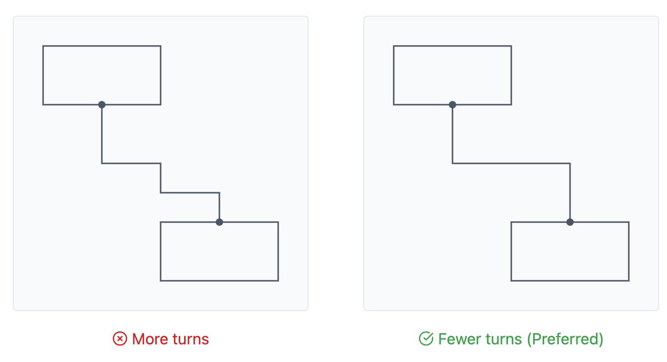
However, multiple shortest paths may exist. Paths with fewer turns looked more pleasing. It's easy to extend BFS to track the number of turns and select the path with fewer turns in case of equal path lengths.
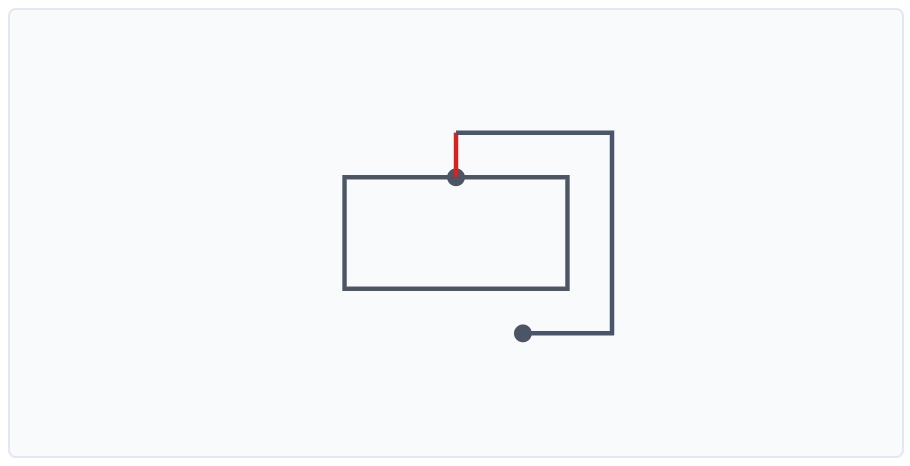
Minimizing turns alone isn't sufficient. Consider the following scenario where both paths are the shortest and have the same number of turns, yet one feels more "balanced":
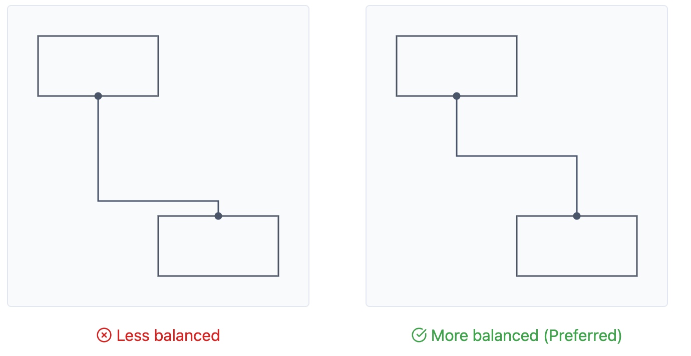
This "balance" can be formalized by seeking the path with the minimal maximum segment length. Among all shortest paths with the fewest turns, select the one where the longest single horizontal or vertical segment is as short as possible. However, tracking this in BFS can be challenging unless all paths are found. In my implementation, a post-processing step is added to balance the path by adjusting points within the spaces between two rectangles. To summarize, the elbow connector can be defined as follows:
    1. The shortest path using only horizontal/vertical segments, avoiding rectangles overlap (except at endpoints).
    2. Among those, the one with the minimal number of turns.
    3. Among those, the one with the minimal maximum segment length.
Other States
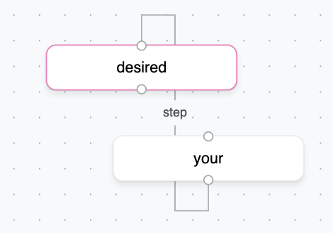
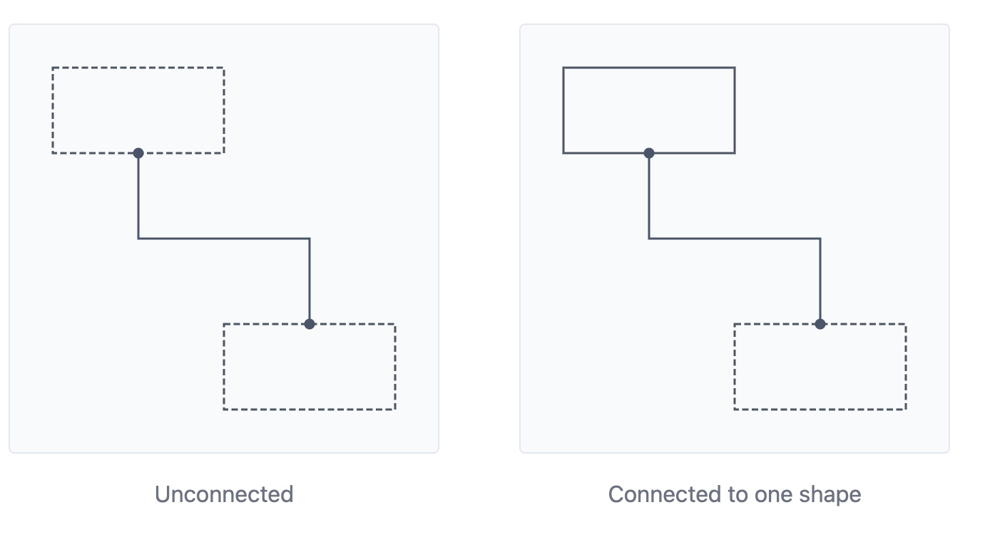
As mentioned earlier, the elbow connector can exist in unconnected or half-connected states. These variations are important to consider in different application contexts.
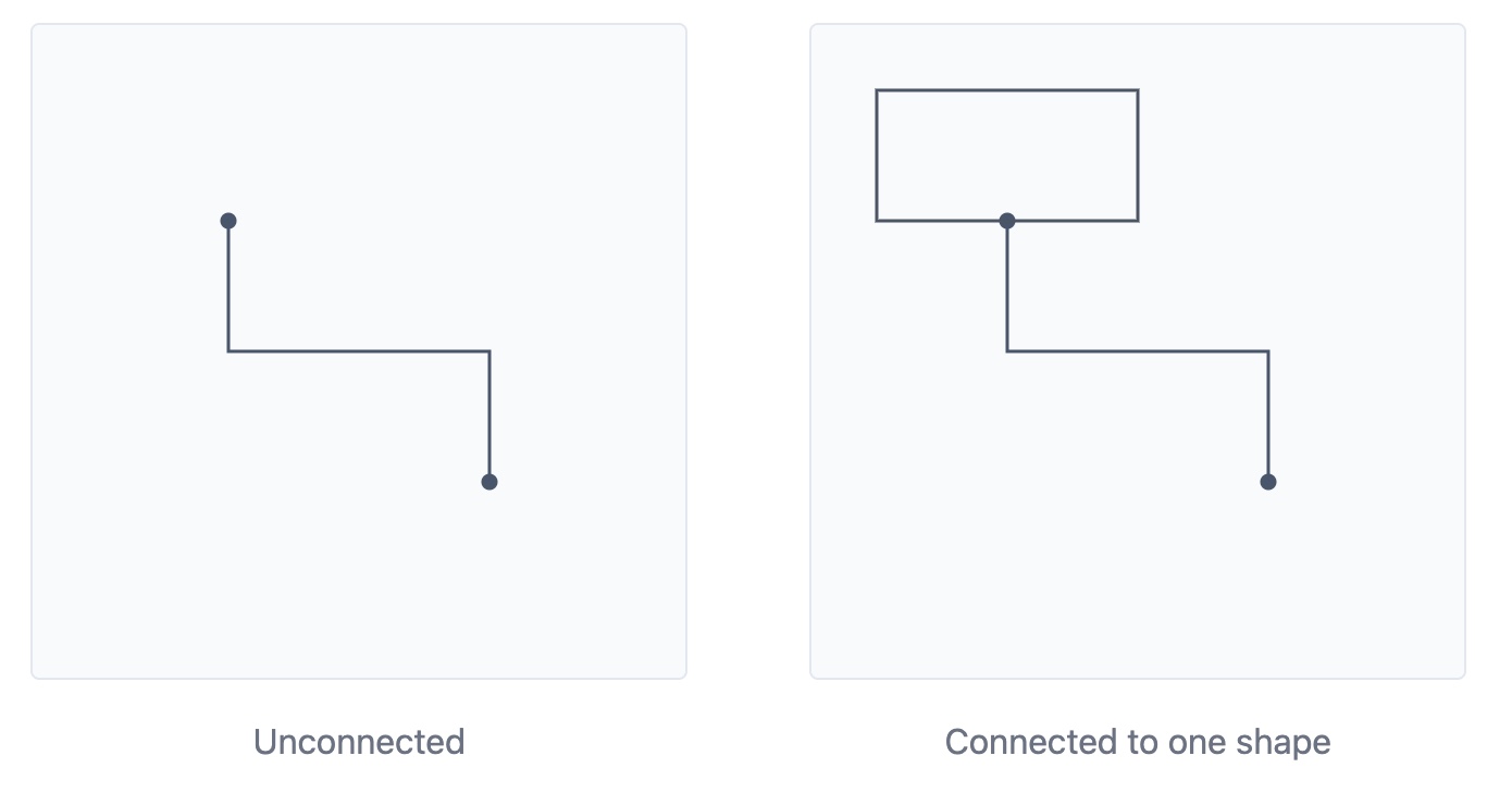
They appear to violate our "minimal turns" rule. However, I found that these cases can be handled by introducing virtual rectangles representing potential connection targets.
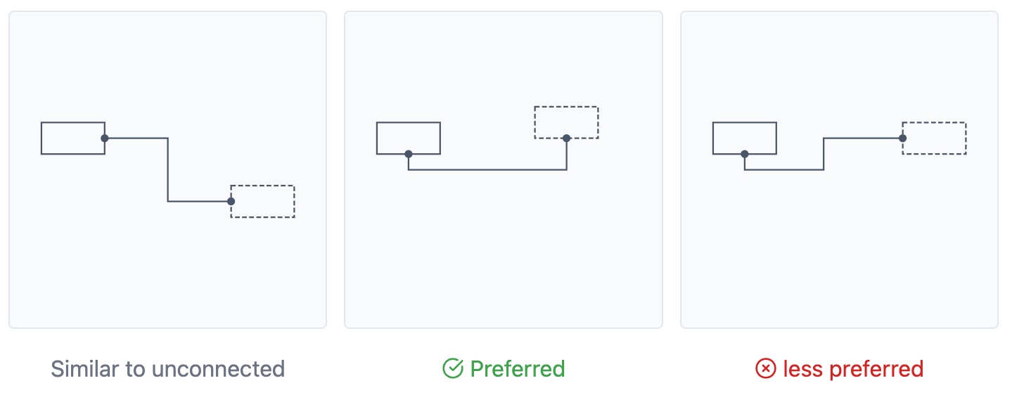
In the unconnected case, the preferred orientation, either vertical or horizontal, depends on which distance is greater: the horizontal or the vertical distance between the two points. In the right example, the connector may feel unnatural without visual rectangles as cues.
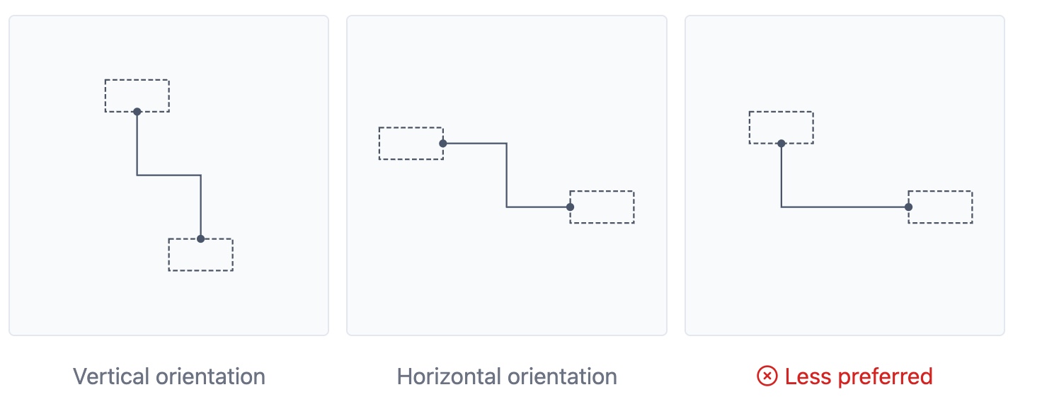
The case of partially connected shapes is more complex, as the preferred orientation depends on the starting point's position on the rectangle. For instance, comparing the middle example and right example, when p1 is located on the bottom edge of the rectangle and p2 is above p1, the vertical orientation looks better even the horizontal distance between two points is larger than the vertical distance.
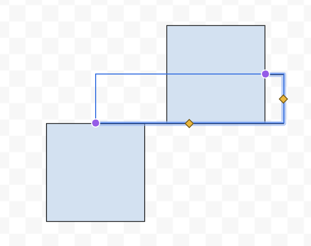
These special cases can be identified by determining whether the rectangle defined byp1 and p2 overlap with rectangle rect1 or rect2, as illustrated in Case 1 and Case 2 below. It turns out these cases lead to shortest path with minimal turns, enabling reuse of previous pathfinding algorithm instead of manually creating virtual rectangles. When there is no overlap between the rectangles, virtual rectangles can be created following the unconnected case.
Conclusion
While elbow connectors are ubiquitous, there lacks a widely agreed-upon definition or even an attempt to define it. I hope this post provides a useful summary and exploration of this UI pattern. To cover all cases, the proposed strategy may seem over-engineered, but it still helps to simplify the implementation compared to hardcoding each case. One limitation is the assumption of a discrete grid and potential performance costs for pathfinding in large spaces, which I will try to address in future work. The source code is available on Github Repo, and all feedback on this post and code is welcome via GitHub issues.